
A vertical extension adds one or more storeys to a building that has to carry them. It is the project least tolerant of wrong drawings: every error about the existing building carries straight through into the new construction. The feasibility study needs data that the archives almost never provide: the real geometry of the roof and its structure, levels and heights to the centimetre, the plumb of the load-bearing façades, the position of the shafts to be extended, the current floor areas. A 3D survey (full laser scan, drone for the roof) and a LOD 300 BIM model of the existing building deliver this data in a single site visit, and become the direct basis for the design, the options and the building permit application.
The details below: what the study must know with certainty, how the survey measures it, and what it costs.
Already have a building in mind? The configurator prices its survey in 2 minutes.
Why a vertical extension forgives no approximation
In French-speaking Switzerland, building land is scarce and spatial planning pushes towards inward densification rather than sprawl. Adding storeys is the most direct answer: creating square metres without consuming a single square metre of land, on plots that are already serviced, in neighbourhoods that already have transport. That is why property management firms, condominium owners and architecture practices are taking a growing interest in it, and why municipalities are seeing more and more such applications.
But a vertical extension has one particularity that neither new construction nor interior renovation shares: everything is built on the existing structure. The new structure brings its loads down into the current walls; the new storeys sit on the current slabs; the new building envelope is measured from the current cornices. A dimension 10 cm off on the level of a cornice, and a storey height no longer fits, an exemption has to be requested, or a project is redrawn after the public consultation.
Yet the drawings most of these studies start from date back to construction (often before 1990) and show neither the successive alterations, nor the real dimensions, nor the deformations of the building. We have documented the scale of the problem in Outdated archive drawings: the hidden risk in your renovation. For an interior renovation, a wrong archive drawing costs surprises on site. For a vertical extension, it can cost the feasibility itself.
What must the feasibility study know with certainty?
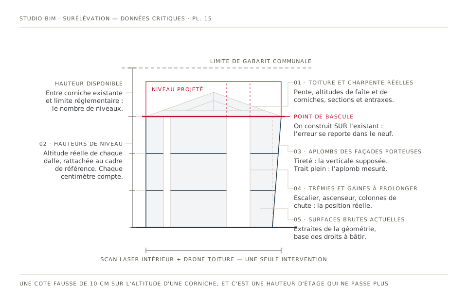
Five families of data, and for each one, the typical gap between what the archives say and what a 3D survey measures:
| Data required | What the archives say | What the 3D survey measures |
|---|---|---|
| Roof and roof structure | Schematic section, often never updated | Real pitch, ridge and cornice levels, measured member sizes and spacings |
| Levels and heights | Nominal construction dimensions | Real level of every slab, tied to the reference frame |
| Load-bearing façades | Assumed vertical | Plumb and out-of-plumb measured to within a few millimetres |
| Shafts and ducts | Original position | Real position after 50 years of alterations |
| Current floor areas | Added up by hand, variable definitions | Extracted from the modelled geometry |
The real roof and roof structure
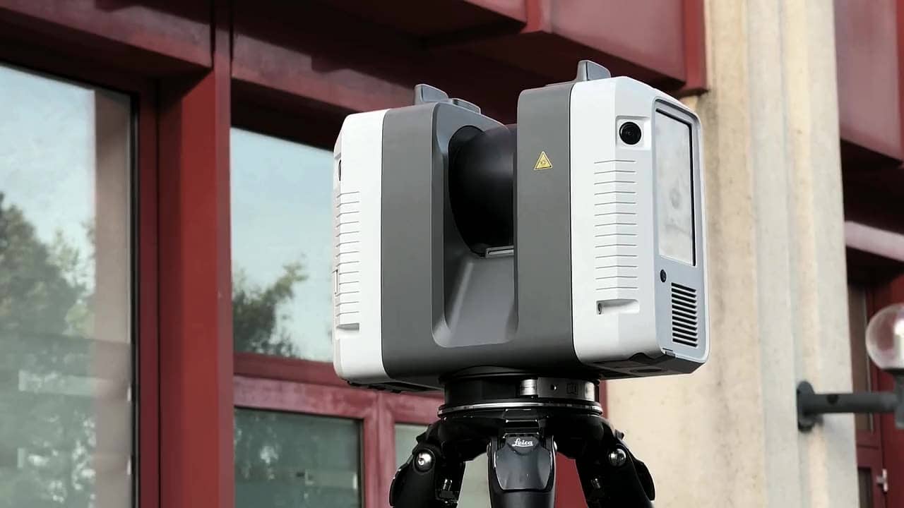
This is the zone the project replaces or transforms, and the least well documented part of the building. The study needs the real pitch, the exact levels of the ridge and of every cornice, the overhangs, the rooftop structures (chimneys, ventilation, lift overruns) and, if there is an attic, the member sizes and spacings of the roof structure. The scanner measures all of this without touching it; the drone completes the picture for the faces that cannot be seen from the ground.
Levels and heights, to the centimetre
The permitted building envelope comes down to centimetres: the height available between the existing cornice and the regulatory limit decides the number of possible storeys, their storey height, and sometimes the feasibility itself. A georeferenced survey ties the building’s levels to the Swiss reference frame, the only solid basis for comparing the existing building against municipal height rules.
The plumb of the load-bearing façades
An old building is never square. Façades lean, have a batter, have deformed over time. The structure of the extension must transfer its loads to where the load-bearing walls actually are, not to where the 1962 drawing shows them. The point cloud gives the plumb of every façade, measured over its full height.
The shafts and ducts to be extended
Stairwell, lift, soil stacks, ventilation: everything that has to rise by one storey must be located exactly in the existing building. A duct offset discovered during the construction phase is one of the classic cost overruns of a vertical extension; it is prevented at the survey stage.
The current floor areas
Residual development rights are calculated from the existing floor areas, according to index definitions that vary from one canton and one municipality to another. Whatever definition applies to your plot, it relies on measured areas, and a structured BIM model makes it possible to extract both the standardised SIA 416 areas and the areas under the regulatory definition requested, provided it is specified.
Attic conversion: the same questions, in a tighter space
Converting an attic is the little sister of the vertical extension: you do not raise the building, you inhabit its last volume. The questions are identical, with one more constraint: the geometry under the sloping roof. The floor area that can actually be used depends on the headroom under rafters and purlins, measured point by point, and regulations set minimum heights for an area to count as habitable. To within 5 cm, a bedroom exists or it does not.
Yet attics are precisely the hardest zone to survey with a tape measure: cluttered roof structure, areas with no floor, inaccessible corners. The scanner is in its element there: from a few stations it measures everything it sees (member sizes, spacings, clear heights, hatches and chimney stacks) without anyone having to crawl along the purlins.
How does the process work, from scan to building permit application?
1. The full scan, attic and roof included
Laser scanner inside (flats, circulation, attic, basement) and around the building; drone photogrammetry for the roof and the upper façades. Accuracy in the region of 2 to 5 mm with the scanner, 1 to 3 cm with the drone, with no scaffolding or cherry picker. Everything is assembled into a single, georeferenced point cloud. One constraint to anticipate: the regulatory framework for drone flights (airport zones, built-up areas), which we factor into the preparation.
2. The LOD 300 BIM model of the existing building
On this point cloud, we model the existing building in Revit or Archicad: walls, slabs, roof, shafts, openings, and the roof structure when the project requires it. LOD 300, our standard deliverable, matches exactly what a vertical extension study needs: accurate, reliable geometry, without superfluous construction detail. The model is delivered in native format and in IFC, together with the point cloud.
3. Designing in the model, not alongside it
This is where the survey changes the nature of the architect’s work: the extension is drawn directly in the model of the existing building. The options (a full storey, a set-back attic storey, a converted attic) are compared on the same geometric basis, with quantities extracted from the model rather than estimated. And the building permit file presents an existing state and a proposed state that are rigorously consistent, cut from the same model.
Condominiums and co-ownership: deciding on indisputable documents
Many vertical extensions concern condominium buildings (PPE). The decision is then taken at the general meeting of co-owners, with questions that cause friction: allocation of shares, valuation of the development rights transferred, floor areas created. A file based on archive drawings is easily challenged, and one challenge is enough to bog a project down for years.
A dated 3D survey and a model of the existing building provide what the meeting needs: before/after areas extracted from the real geometry, verifiable by any consultant appointed by the co-owners. For the property management firms steering these files, it is a governance document as much as a technical one.
How much does surveying a building before a vertical extension cost?
Figures from our public rate card, for the 3D survey + LOD 300 BIM model service:
- 1,500 m² building: CHF 7’750, delivered in 16 to 20 working days.
- General range: around CHF 3 to 11 per m² depending on floor area (decreasing with area), minimum order CHF 1’350.
- SIA 416 area report option (the before/after for the general meeting or the calculation of development rights): +10% on the service portion.
At the scale of a vertical extension, a project counted in millions, the survey weighs a fraction of a percent of the construction cost. A single envelope or roof-structure error avoided pays for it several times over.
Frequently asked questions
What data do you need to study adding storeys to a building?
Five families: the real geometry of the roof and its structure, the exact levels and heights (cornices and ridge included, as levels tied to the reference frame), the plumb of the load-bearing façades, the position of the shafts and ducts to be extended, and the current floor areas for calculating development rights. A 3D survey captures all five in one site visit.
Can a roof be scanned without scaffolding?
Yes. Drone photogrammetry surveys roofs, chimney stacks and upper façades with an accuracy in the region of 1 to 3 cm, and the laser scanner completes the picture from the ground, the attic or neighbouring buildings. The weather and flight restriction zones still have to be factored in: points of preparation, not obstacles.
Which LOD for a vertical extension project?
LOD 300, our standard deliverable: the geometry of the existing building is accurate and reliable (walls, slabs, roof, shafts) without construction detail that is unnecessary at this stage. The roof structure is modelled in addition when an attic project requires it. A higher level can be discussed at quote stage if construction requires it.
How much does surveying a building before a vertical extension cost?
For a 1,500 m² building, expect CHF 7’750 for a 3D survey + LOD 300 BIM model, delivered in 16 to 20 working days. The general order of magnitude runs from around CHF 3 to 11 per m² depending on floor area. The configurator gives the exact price for your building in 2 minutes.
Is a survey enough to prove structural feasibility?
No. The survey gives the exact geometry (plumb, member sizes, levels), but load-bearing capacity is the domain of the structural engineer, who will need investigations of the structure. The two complement each other: the engineer works far faster and far more accurately on a model of the existing building than on archive drawings.
The existing building to the centimetre, before drawing the extra storey. Price the survey of your building in 2 minutes: studiobim.ch/devis.